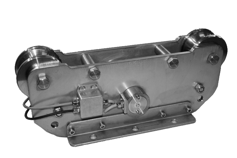
TR.DI.CO ist ein Tensiometer für gleitende Seile mit Überlastfunktion. Er ist “made in Europe” und trägt das CE-Kennzeichen. Ideal für die Installation an neuen und schon vorhandenen Winden, da die Installation äußerst einfach und ohne Abtrennung des Seils erfolgt.
Wie der gleichnamige nordische Riese, ist TR.DI.CO stark, robust und besonders für extreme Umgebungsbedingungen geeignet. Die kompakte Struktur, das sorgfältige Design und die hohe Zuverlässigkeit machen aus diesem Tensiometer ein unentbehrliches Instrument zur Kontrolle und Sicherheit von Seilzuganlagen. Die Standardausführungen der Modelle TR.DI.CO decken einen Leistungsbereich von 0 bis 500 Tonnen mit Seildurchmessern von bis zu 120 mm.
Die Struktur des TR.DI.CO ist aus Edelstahl. Die Seilspannung wird mithilfe der Wägezelle mit Messbolzen aus Edelstahl gemessen, der ausgezeichnete elastische Eigenschaften besitzt.
| Model | Gewicht | Max Spannung | Seil Max |
Größe (cm ): |
| TR.DI.CO 5K |
7 kg | 5.000 daN | 20 mm | 28x18x18(h) |
| TR.DI.CO 25K |
15 kg | 25.000 daN | 40 mm | 48x16x18,5(h) |
| TR.DI.CO 50K |
50 kg | 50.000 daN | 50 mm | 48x25x38(h) |
Pin Wägezelle: Zertifikat CE, ATEX oder IECEx auf Anfrage
![]() Zur Vergrößerung auf das Bild klicken
Zur Vergrößerung auf das Bild klicken


| Material | Edelstahl |
| Nennlast | 5, 25, 50 t |
| Grenzlast | 150 % F.S. |
| Bruchlast | 300 % F.S. |
| Speisespannung | Max. 15 V dc (option 24 V cd) |
| Ausgangssignal | 1 mV/V (option 4-20 mA) |
| Ausgangstoleranz | 0,1 % F.S. |
| Nulltoleranz | 1 % F.S. |
| Linearität | 0,2 % F.S. |
| Hysterese | 0,2 % F.S. |
| Wiederholbarkeit | 0,2 % F.S. |
| Eingangswiderstand | 350-360 ohm |
| Ausgangswiderstand | 350-353 ohm |
| Isolationswiderstand | >= 2000 Mohm |
| Kriechfehler (30 Minuten) | 0,2 % F.S. |
| Thermische Kompensation | -10 / +40°C (14 / +104°F) |
| Betriebstemperatur | -20 / +70°C (-4 / +158°F) |
| Temperaturabweichung Nullpunkt | 0,003 % F.S. / °C |
| Temperaturabweichung Endwert | 0,002 % F.S. / °C |
| Schutzklasse | IP 67 |
| Standard Kabellänge | 5 m – 4 x 0,25 (Abschirmung nicht mit dem Gehäuse der Wägezelle verbunden) |
| Typ | Elektrokabel Standard (4x0, 25) |
| Länge | 5 m (Bildschirm nicht mit dem Körper der Wägezelle verbunden) |
| Rot | + REF |
| Schwarz | - REF |
| Grün | + OUT |
| Weiß | - OUT |
General precautions to be followed in the installation and assembly of load cells: