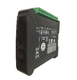
Gewicht Transmitter mit direktem Anschluss von einem oder mehreren Wägezellen und einer Vielzahl von Ausgängen für eine einfache Integration in jedes Industrie- und Automatisierungssystem. Komfortable und sofortige Montage auf DIN-Bar und / oder OMEGA Bar.
DIGITALER MESSVERSTÄRKER für Wägezellen
![]() Zur Vergrößerung auf das Bild klicken
Zur Vergrößerung auf das Bild klicken

| Stromversorgung | 24 V Gleichstrom ± 10% Stromversorgung gegen Verpolung und mit rückstellbarer Sicherung geschützt | |
| Stromaufnahme max | 1,2 W | |
| Betriebstemperatur | -10 / +50 °C (14 / 122 °F) Maximal 85% nicht kondensierend | |
| Lagertemperatur | -20 / +60°C (-4 / +140°F) | |
| Led | 2 LEDs zur Anzeige von Einstellvorgängen | |
| Tastatur | Tastatur bestehend aus 3 Tasten | |
| Außenmaße | 120 x 105 x 24 mm / 4.72 x 4.13 x 0.94 in | |
| Montage | Halterung DIN od. OMEGA Leiste | |
| Anschlüsse | Herausnehmbare Schraubklemme, Rastermaß Schraubklemmen 5.08 | |
| Eigenschaften des Zelleneingangs | Maximal 4 Zellen mit 350 Ω parallel geschalten(oder 8 Zellen mit 700 Ω) | |
| Stromversorgung der Wägezellen | 4 V | |
| Linearität | 0.01% des Skalenendwertes | |
| Temperaturabweichung | < 0.001% des Skalenendwert/°C | |
| Messbereich | Von -3,0 mV/V bis +3,0 mV/V | |
| Digitalfilter | 8 Filterpositionen + 8 Rampeneinstellungen | |
| Kalibrierung des Nullpunkts und Skalenendwert | Über Tasten ausführbar | |
| Analogausgang unter Spannung | ± 10 V / ± 5 V | |
| Auflösung | 16 bit | |
| Kalibrierung | Digital über Tastatur | |
| Impedanz | ≥ 10 kΩ | |
| Linearität | 0.03% des Skalenendwert | |
| Temperaturabweichung | < 0,002 % des Skalenendwert/°C | |
| Analogausgang unter Strom | 0 – 20 A / 4 – 20 mA | |
| Auflösung | 16 bit | |
| Kalibrierung | Digital über Tastatur | |
| Impedanz | ≤ 300 Ω | |
| Linearität | 0.03% des Skalenendwert | |
| Temperaturabweichung | < 0,002 % des Skalenendwert/°C | |
| Normkonform | Normen-Konformität EN61000-6-2, EN61326-1 | |
| Typ | Klemmleiste 7P Schritt 5.08 mm |
| Länge | ND |
| 1 | Shield |
| 2 | - Exc. Load cell |
| 3 | + Exc. Load cell |
| 4 | + Reference |
| 5 | - Reference |
| 6 | - Signal |
| 7 | + Signal |
| Typ | |
| Länge | ND |
| 8 | NC |
| 9 | NC |
| 10 | NC |
| 11 | + Power supply 24 V dc |
| 12 | Ground power supply |
| 13 | Shield / Ground |
| 14 | Common Ground analog outputs |
| 15 | OUT mA |
| 16 | OUT Volts |
General precautions to be followed in the installation and assembly of load cells: