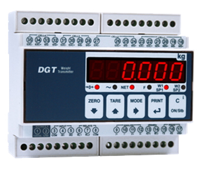
Gewicht Transmitter mit direktem Anschluss von einem oder mehreren Wägezellen und einer Vielzahl von Ausgängen für eine einfache Integration in jedes Industrie- und Automatisierungssystem. Komfortable und sofortige Montage auf DIN-Bar und / oder OMEGA Bar.
4-KANAL DIGITAL SENDER / ANZEIGE
![]() Zur Vergrößerung auf das Bild klicken
Zur Vergrößerung auf das Bild klicken

| Stromversorgung | 12 – 24 V DC ± 10%, stabilisiert | |
| Stromaufnahme max | 100 mA @ 12 V, 70 mA @ 24 V | |
| Betriebstemperatur | -10 / +40°C (14 °F / 104°F) | |
| Display | 6 LED Ziffern, h 13 mm | |
| Led | 6 LED Statusanzeigen | |
| Tastatur | Wasserdicht mit 5 Tasten | |
| Montage | Auf DIN Leiste | |
| Gehäusematerial | Plastik | |
| Eigenschaften des Zelleneingangs | 4 Zellen mit digitaler Entzerrung oder 4 unabhängige Wägesysteme (maximal 16 Zellen mit 350 Ω) | |
| Stromversorgung der Wägezellen | 5 V Gleichstrom ± 5 %, 120 mA (maximal 16 Wägezellen mit 350 Ω | |
| Eingangsempfindlichkeit | Max 6 mV/V | |
| Serielle Schnittstelle | RS485 bidirektional. Konfigurierbar für den Anschluss an PC / SPS oder Gewichtsanzeige | |
| Typ | |
| Länge | ND |
| 1 | + power supply 12/24 V dc |
| 2 | 0 V dc (GND) |
| 3 | NC |
| 4 | NC |
| 5 | NC |
| 6 | NC |
| 7 | NC |
| 8 | NC |
| 9 | NC |
| 10 | NC |
| 11 | NC |
| 12 | NC |
| 13 | RS485 + |
| 14 | RS485 - |
| 15 | RS232 TX |
| 16 | RS232 RX |
| 17 | RS232GND |
| Typ | |
| Länge | ND |
| 18 | + Signal Cell 1 |
| 19 | - Signal Cell 1 |
| 20 | + Reference (only cell 1) |
| 21 | - Reference (only cell 1) |
| 22 | + Power supply Cell 1 |
| 23 | - Power supply Cell 1 |
| 24 | + Signal Cell 2 |
| 25 | - Signal Cell 2 |
| 26 | + Power supply Cell 2 |
| 27 | - Power supply Cell 2 |
| 28 | + Signal Cell 3 |
| 29 | - Signal Cell 3 |
| 30 | + Power supply Cell 3 |
| 31 | - Power supply Cell 3 |
| 32 | + Signal Cell 4 |
| 33 | - Signal Cell 4 |
| 34 | + Power supply Cell 4 |
| 35 | - Power supply Cell 4 |
General precautions to be followed in the installation and assembly of load cells: