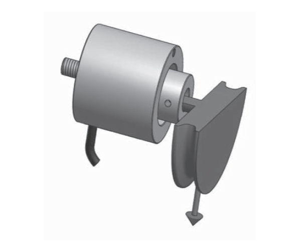
RIEMENSCHEIBEN-WÄGEZELLE
Eigenschaften: Kompakt, hervorragende Auflösung. Einfach zu montieren, hohe Resonanzfrequenz. Schutz vor Überlastung.
Anwendungen: Wickelmaschinen, Aufspuler, Abwickler, Drahtspanner und jede andere Anwendung bei der die Zugkraft von Kabeln, Bändern, Optikfasern, Textilfäden usw. gemessen werden muss.
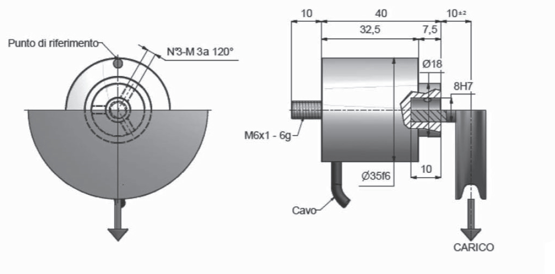
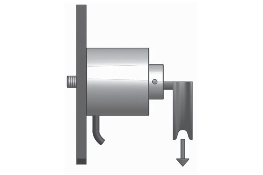
![]() Zur Vergrößerung auf das Bild klicken
Zur Vergrößerung auf das Bild klicken


| Material | Aluminium/Stahl |
| Nennlast | 2.5, 5, 10, 25, 50, 75, 100 N |
| Grenzlast | 300 % F.S. |
| Bruchlast | 500 % F.S. |
| Messweg bei Nennlast | 0,12 mm |
| Speisespannung | Maximal 18 V Gleichstrom |
| Empfindlichkeit | 1 mV/V |
| Ausgangstoleranz | 0,2 % F.S. |
| Nulltoleranz | 1 % F.S. |
| Linearität | 0,1 % F.S. |
| Hysterese | 0,2 % F.S. |
| Wiederholbarkeit | 0,2 % F.S. |
| Eingangswiderstand | 350-360 ohm |
| Ausgangswiderstand | 350-353 ohm |
| Isolationswiderstand | >= 2000 Mohm |
| Kriechfehler (30 Minuten) | 0,03 % F.S. |
| Thermische Kompensation | -10 / +40°C (14 / +104°F) |
| Betriebstemperatur | -20 / +70°C (-4 / +158°F) |
| Temperaturabweichung Nullpunkt | 0,003 % F.S. / °C |
| Temperaturabweichung Endwert | 0,002 % F.S. / °C |
| Schutzklasse | IP 54 |
| Standard Kabellänge | 3 m – 4 x 0,15 (Abschirmung nicht mit dem Gehäuse der Wägezelle verbunden) |
| Typ | GESCHIRMTES KABEL 4C PVC R3 4X0,15 |
| Länge | 3 m (Bildschirm nicht mit dem Körper der Wägezelle verbunden) |
| Rot | + IN |
| Schwarz | - IN |
| Grün | + OUT |
| Weiß | - OUT |
General precautions to be followed in the installation and assembly of load cells: