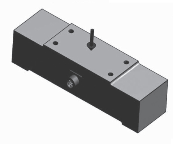
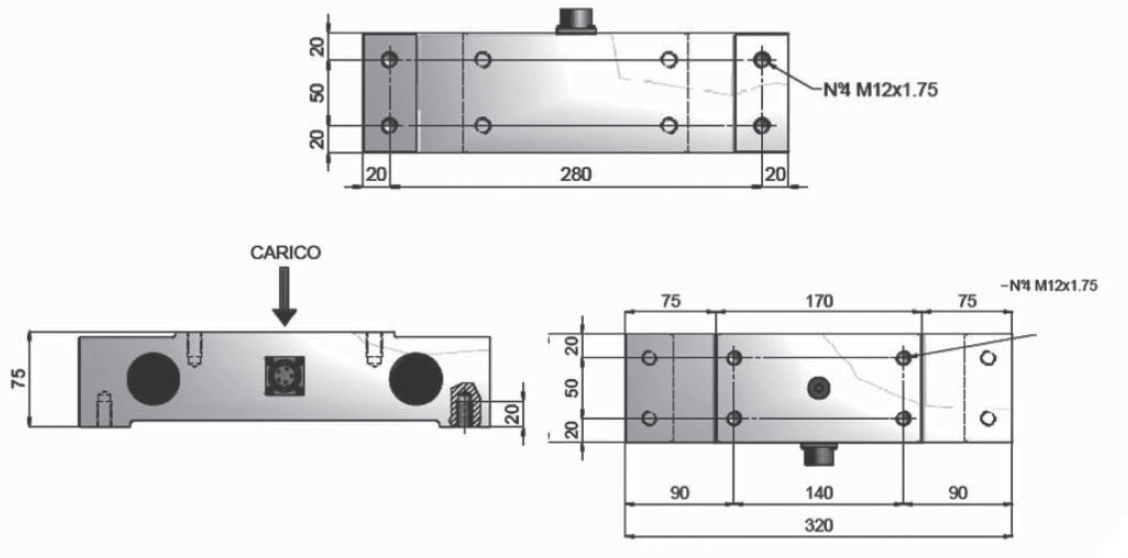
ROLLEN-WÄGEZELLE
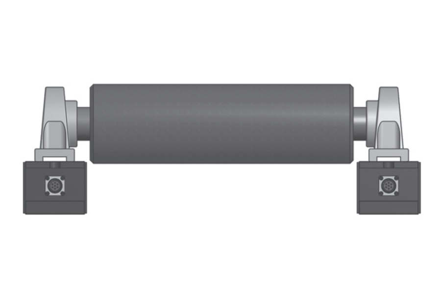
Eigenschaften: Wägezelle für gerade Träger. Unempfindlich gegen Belastungen in 2 Achsen ausgenommen der Messachse. Schutz vor Überlastung.
Anwendungen: Um die Zugkraft von Textilien, Papier, Gummi, Kunststoff, Metalllaminaten, usw. zu messen.
![]() Zur Vergrößerung auf das Bild klicken
Zur Vergrößerung auf das Bild klicken


| Material | Aluminium/Edelstahl |
| Nennlast | 10, 15, 20, 30, 50, 75, 100 kN |
| Grenzlast | 200 % F.S. |
| Bruchlast | 500 % F.S. |
| Messweg bei Nennlast | 0,10 mm |
| Speisespannung | Maximal 18 V Gleichstrom |
| Empfindlichkeit | 1 mV/V |
| Ausgangstoleranz | 0,1 % F.S. |
| Nulltoleranz | 1 % F.S. |
| Linearität | 0,1 % F.S. |
| Hysterese | 0,03 % F.S. |
| Wiederholbarkeit | 0,15 % F.S. |
| Eingangswiderstand | 350-360 ohm |
| Ausgangswiderstand | 350-353 ohm |
| Isolationswiderstand | >= 2000 Mohm |
| Kriechfehler (30 Minuten) | 0,03 % F.S. |
| Thermische Kompensation | -10 / +40°C (14 / +104°F) |
| Betriebstemperatur | -20 / +70°C (-4 / +158°F) |
| Temperaturabweichung Nullpunkt | 0,003 % F.S. / °C |
| Temperaturabweichung Endwert | 0,002 % F.S. / °C |
| Schutzklasse | IP 65 |
| Anschlüsse | Panel-Stecker CR2R-07APNS |
| Standard Kabellänge | Loser Gegenstecker CR2P-07ASNS-10, Verbindungskabel 6 x 0,35 (Länge zu definieren) |
| Typ | VERBINDER MIL 4P IT3106A-14S |
| Länge | 5 - 10 m (Bildschirm nicht mit dem Körper der Wägezelle verbunden) |
| Pin A | - IN |
| Pin B | - OUT |
| Pin C | + OUT |
| Pin D | + IN |
| Option | VERBINDER 4P 4-20 mA S154 |
| Länge | 5 - 10 m (Bildschirm nicht mit dem Körper der Wägezelle verbunden) |
| Pin A | 4 mA |
| Pin C | 20 mA |
General precautions to be followed in the installation and assembly of load cells: