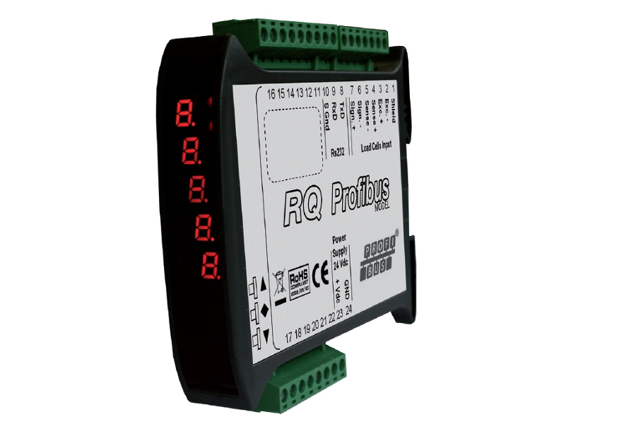
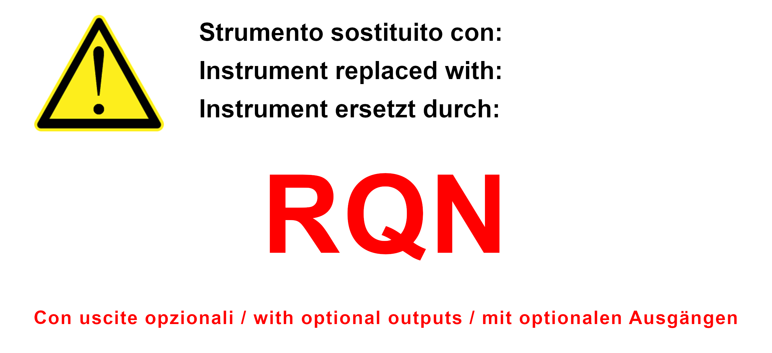
Digital VERSTÄRKER mit Profibus DP-V1 Schnittstelle
Display mit Led, 7 rote Segmente, 5 Zeichen h 7 mm, Tastatur, 3 mechanische Tasten.
Integrierte Kommunikationsschnittstellen Rs232, Feldbus Profibus DP-V1.
Bedienungsanleitung herunterladen ![]()
![]() Zur Vergrößerung auf das Bild klicken
Zur Vergrößerung auf das Bild klicken


| Stromversorgung | 24 V Gleichstrom ± 10% gegen Umpolung geschützt, Schutz mit rücksetzbarer Sicherung | |
| Stromaufnahme max | 2 W | |
| Isolierung | Klasse II | |
| Installationskategorie | Kategorie II | |
| Betriebstemperatur | -10 / +50 °C (14 / 122 °F) Maximal 85% nicht kondensierend | |
| Lagertemperatur | -10 / +60°C (-4 / +140°F) | |
| Display | Numerisch mit 5 roten LED Anzeigen mit je 7 Segmenten (h 7 mm) | |
| Led | 2 LED mit 3 mm | |
| Tastatur | 3 Tasten (hinter Frontverkleidung) | |
| Außenmaße | 110 mm x 120 mm x 35 mm / 4.33 x 4.72 x 1.38 in (l x h x p) | |
| Montage | Halterung DIN oder OMEGA Leiste | |
| Gehäusematerial | Mix ABS/PC selbstverlöschend | |
| Anschlüsse | Herausnehmbare Schraubklemme. Rastermaß Schraubklemme 5.08 mm | |
| Eigenschaften des Zelleneingangs | Maximal 4 Zellen mit 350 Ω parallel geschalten(oder 8 Zellen mit 700 Ω) | |
| Stromversorgung der Wägezellen | 4 V | |
| Linearität | < 0.01% des Skalenendwertes | |
| Temperaturabweichung | < 0.001% des Skalenendwertes/C° | |
| Interne Auflösung | 24 bit | |
| Messbereich | Von -2,6 mV/V bis +2,6 mV/V | |
| Ausgaberate | Von 4 Hz bis 123 Hz | |
| Gewichts-Dezimalzahlen | Von 0 bis 3 Dezimalstellen | |
| Kalibrierung des Nullpunkts und Skalenendwert | Über Tasten durchführbar | |
| Kontrolle Zellenkabelunterbrechung | Fortlaufend | |
| Serielle Schnittstelle | Rs232 half duplex | |
| Maximale Kabellänge | 15m (Rs232c) | |
| Baudrate | 1200, 2400, 4800, 9600, 19200, 38400, 115200 wählbar | |
| Feldbus | PROFIBUS DP-V1: baud rate Von 9,6 kbit/sec bis 12 Mbit/sec | |
| Normkonform | Konformität EMC Normen: EN61000-6-2, EN61000-6-3, Konformität elektrische Sicherheit: EN61010-1 | |
| Typ | Klemmleiste 7P Schritt 5.08 mm Ausführung 6-Draht-Wägezelle |
| Länge | ND |
| 1 | Shield |
| 2 | - Excitation |
| 3 | + Excitation |
| 4 | + Reference |
| 5 | - Reference |
| 6 | - Signal |
| 7 | + Signal |
| Typ | Klemmleiste 9P Schritt 5.08 mm Profibus |
| Länge | ND |
| 8 | RS232 Tx |
| 9 | RS232 Rx |
| 10 | RS232 GND |
| 11 | NC |
| 12 | NC |
| 13 | NC |
| 14 | NC |
| 15 | NC |
| 16 | NC |
| Typ | Klemmleiste 8P Schritt 5.08 mm Profibus |
| Länge | ND |
| 17 | NC |
| 18 | NC |
| 19 | NC |
| 20 | NC |
| 21 | NC |
| 22 | NC |
| 23 | Power supply 24 Vdc |
| 24 | Power supply 0 Vdc |
General precautions to be followed in the installation and assembly of load cells: