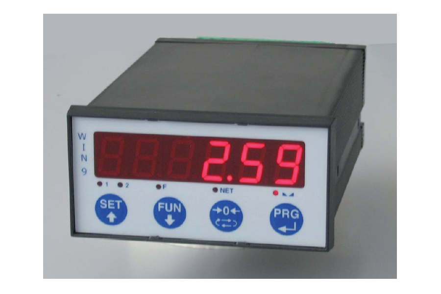
Gicam Gewicht-Indikatoren sind Gewichtanzeiger-Geräte, die mit Wägezellen verbunden sind. Wir haben Multifunktionsdisplayer zum Wiegen und Dosieren, zum Brückenwägen, mit Lastbegrenzer. Tragbare Displays sind in bequemen Aktentaschen erhältlich. Wir haben Panel-Montage, tragbare, DIN und OMEGA Bar Halterungen, analoge Indikatoren und Touchscreens Anzeigen. IP65 Produkte sind mit Staubschutz erhältlich. Gicam Indikatoren unterstützen industrielle Kommunikationsprotokolle wie PROFIBUS, PROFINET, MODBUS und vieles mehr.
Anzeige
Bedienungsanleitung herunterladen ![]()
![]() Zur Vergrößerung auf das Bild klicken
Zur Vergrößerung auf das Bild klicken

| Stromversorgung | 24 Vcc ± 15% | |
| Stromaufnahme max | 5 W | |
| Isolierung | Klasse II | |
| Installationskategorie | Cat. II | |
| Betriebstemperatur | -10 / +40 °C (Feuchte max 85% nicht kondensierend) | |
| Lagertemperatur | -20 / +50 °C | |
| Display | Numerisch 6 Zeichen, rote Led, 7 Segmente (h 14 mm) | |
| Led | 5 Ledanzeigen zu 3 mm | |
| Tastatur | 4 mechanische Tasten | |
| Außenmaße | 96 mm x 48 mm x120 mm (l x h x p) | |
| Montage | Zum Einbauen in die Tafel (Bohrschablone 91 mm x 44 mm) | |
| Gehäusematerial | Noryl, selbstlöschend (UL 94 V1) | |
| Schutzklasse | IP 54 | |
| Anschlüsse | Abnehmbare Schraubenklemmleisten Schritt 5.08 | |
| Stromversorgung der Wägezellen | 5 Vcc / 90mA mA (max. 6 Zellen zu 350 ohm parallel) vor Kurzschluss geschützt | |
| Eingangsempfindlichkeit | 0.02 µV min | |
| Linearität | < 0.01% des Endanschlags | |
| Temperaturabweichung | < 0.001% des Endanschlags / C° | |
| Interne Auflösung | 24 bit | |
| Gewichtsauflösung | Bis zu 60.000 Teilungen an der nützlichen Leistung | |
| Messbereich | -3.9 mV/V - +3.9 mV/V | |
| Häufigkeit der Gewichtserfassung | 6 Hz - 50 Hz | |
| Digitalfilter | Anwählbar 0.1 Hz - 25 Hz | |
| Gewichts-Dezimalzahlen | von 0 bis 3 Dezimalzahlen | |
| Kalibrierung des Nullpunkts und Skalenendwert | (Theoretische) Automatik oder über Tastatur durchführbar | |
| Analogausgang unter Spannung | Option: ± 10 V / ± 5 V | |
| Auflösung | 16 bits | |
| Kalibrierung | Digital über Tasten | |
| Impedanz | Min. 10Kohm | |
| Linearität | 0.03% des Endanschlags | |
| Temperaturabweichung | 0.001% des Endanschlags / °C | |
| Analogausgang unter Strom | Option: 0 - 20 mA / 4 - 20 mA | |
| Auflösung | 16 bits | |
| Kalibrierung | Digital über Tasten | |
| Impedanz | Max. 300 ohm | |
| Linearität | 0.03% des Endanschlags | |
| Temperaturabweichung | 0.001% des Endanschlags / °C | |
| Logische Ausgänge | 2 optoisoliert (reiner Kontakt) je max. 24Vdc / 60 mA | |
| Logische Eingänge | 2 optoisoliert zu 24 Vcc PNP (äußere Speisung) | |
| Serielle Schnittstelle | Rs232c / Rs422 / Rs485 half duplex | |
| Maximale Kabellänge | 15m (Rs232c) und 1000m (Rs422 und Rs485) | |
| Serielle Protokolle | ASCII, Modbus | |
| Baudrate | 2400 / 9600 / 19200 / 38400 / 115000 | |
| Speicher Programmcodes | 64 Kbytes FLASH erneut programmierbar on board über RS232 | |
| Datenspeicher | 2 Kbytes | |
| Normkonform | EN50081-1, EN50082-2, EN61010-1 | |
| Typ | Klemmleiste 12P Schritt 5.08 |
| Länge | ND |
| 1 | + 24 Vcc Power supply |
| 2 | - 24 Vcc Power supply |
| 3 | Analog current output 0-20mA/4-20mA Max 300 ohm |
| 4 | Analog vltage output 0-5V/ 0-10V min 10Kohm |
| 5 | Negative analog output Voltage/Current |
| 6 | RS232 Tx |
| 7 | RS232 Rx |
| 8 | GND |
| 9 | RS485 TX+ |
| 10 | RS485 TX- |
| 11 | RS485 RX+ |
| 12 | RS485 RX- |
| Typ | Klemmleiste 12P Schritt 5.08 |
| Länge | ND |
| 13 | Output 1 |
| 14 | Output 2 |
| 15 | Common output |
| 16 | + Input 1 |
| 17 | + Input 2 |
| 18 | Common input |
| 19 | - Exc. Load cell |
| 20 | + Exc. Load cell |
| 21 | + Load cell Sense |
| 22 | - Load cell Sense |
| 23 | - Signal load cell |
| 24 | + signal load cell |
General precautions to be followed in the installation and assembly of load cells: